
Mixed Signal & Domain Simulation for Embedded Worlds
The Easiest Way of Simulating C/C++ Code Together with an Analog & Digital Spice Simulation
In previous articles we saw how to perform a mixed signal domain analogue, digital with a verilog spice simulation, cross-platform schematics entry, and blender for the visualization and animation of the mechatronics movements. In this article, we move further and learn on a very basic circuit of a MCU controlled current (force) control loop of a DC motor, about how to make a spice simulation even more comprehensive by embedding an actual C/C++ code in a unique way that requires no-modifications from the original code that runs on MCU or DSP platforms. We will see how the NgSpice version of Spice Simulator becomes an indispensable development framework for the algorithm & embedded firmware developers, the system simulation, and the unit testing of real circuits.
Uros Platise, 8 April 2018
Consider a firmware development for Power Control Algorithms like Power Conversion (DC/DC, PFC, LLC), PMSM Three Phase Sensor-Less Motor Control, or Control Algorithms for Automotive applications, Fuzzy Logic Controllers, or even High-end Data-Acquisition. All of them combine knowledge from analogue, digital, signal processing, and embedded firmware development.
A firmware developer may not necessarily be the same person who designed the analogue or power part of the project. Burning a MOSFET is not just about this, but it means time needed for repairs and associated damage costs.
Having a system simulation environment for firmware development therefore represents a clear benefit. If such a framework does not require actual changes in the code, which can be run as unit tests and with a full debug possibility, then this clearly shortens the time of the development, broadening the test coverage to test cases that are hard to test even in practice, and the tests can be integrated in a Continuous Integration System such as is Jenkins.
The simulation flow shown in this article uses Eagle for schematics drawings with the Isotel conversion to the ngspice netlist. However, the use of ngspice with the presented firmware development is not limited to it and may run completely independently and on all operating systems, including Windows. To keep the article short, very basic and limited models are used, simplification is applied whenever possible; however, overall, the project structure reflects a real project.
The Tools
Besides the tools mentioned under the Conceptual Simulation of a Digital Sine Generator from Eagle, we also need:
Isotel NgSpice Fork: Digital Process (d_process)
Isotel NgSpice Fork in addition to the latest ngspice master branch provides Isotel d_process the xspice code-model for a simple integration of the external independent digital synchronous processes into a transient simulation.
Quick Integration of the External Code with No Learning Curve
Use of your favourite debugging tools
Any Language: C, C++, python, …
Any Processor, with Cross-Development Tools
Any Platform, direct integration of MCUs into NgSpice environment
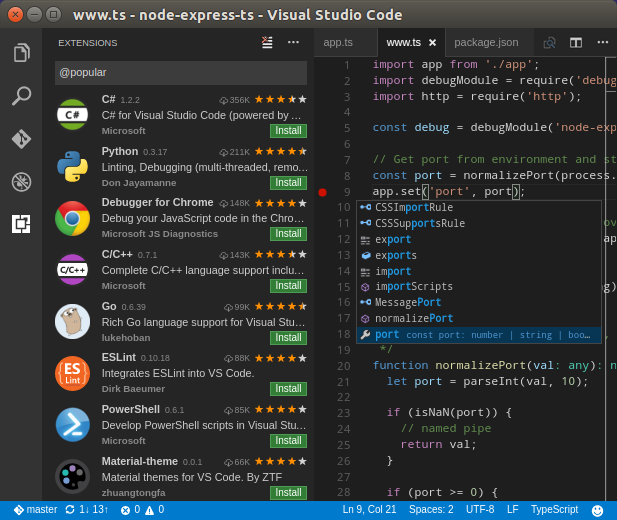
Recommendation: Visual Studio Code
Visual Studio Code is a lightweight, but powerful source code editor that runs on your desktop and is available for Linux, macOS and Windows.
Fast Start-up, Responsive, Extensible
Intelligent Code Completion
Streamlined Debugging
Fast, Powerful Editing
Code Navigation and Refactoring
In-Product Source Control
Digital Force (Current) Motor Controller
In the article Conceptual Simulation of a Digital Sine Generator from Eagle, we showed a conceptual simulation without building a real hardware at the end. Here, we will go in the opposite direction, which is more common in real-life scenarios, by:
First, designing a very basic schematics around a PSoC5 ARM based micro-controller with a high-side current sense and a single quadrant power source.
In the next step, we model the inside of the micro-controller with analogue circuitry directly in the spice, PWM in Verilog with a digital interface to the ARM processor.
Then, we design a very basic control algorithm in C that regulates the motor current and consequently its force.
As the last step, we set a test bench, compile it, and run it within the simulation or as an external process with full debugging capabilities.
Electric Circuit
Let’s design a very basic schematics that drives a 5 V DC motor out of a USB port in Eagle CAD (a different EDA tool could be used if it can generate an appropriate ngspice compatible netlist).

We have used:
a powerful Mixed Signal Cortex-M3 Cypress PSoC5 as the core surrounded by power supplies blocking capacitors,
a low side mosfet switch driven directly by PSoC5 8-bit PWM,
and a floating rail-to-rail current sense to be sensed directly by a 12-bit SAR differential input.
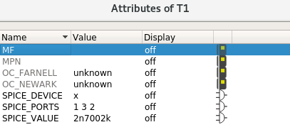
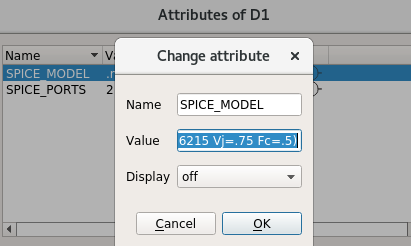
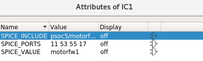
To make this realistic circuit ready for simulation we annotated it with these attributes:
SPICE_IGNORE to eliminate all the parts we are not interested in simulating,
SPICE_MODEL to diode D1 and reverse A,B pads to match the polarity of the diode,
SPICE_DEVICE property to the transistor, which also needs to have pins 2 and 3 swapped to fit a spice model using SPICE_PORT,
SPICE_PORTS to select pins of PSoC5 of our interest in the simulation and ignore the rest.
To keep the schematics clean and ready for PCB design, we are not going to place voltage sources on it, but rather export its connections and use it as a component in a test bench. We add a:
SPICE_PORT device next to the USB Vcc and GND power, and provide motor connections, to the same points as an actual motor would go.
More about the test bench later on; now, let’s go inside the PsoC5 and prepare for firmware development.
Inside the Cypress PSoC5
PSoC5 is an extremely flexible micro-controller that features re-programmable digital and analogue blocks in addition to Cortex-M3 ARM. it’s so flexible its pin-out allow almost any function to be wired to almost any pin. It greatly simplifies PCB routing with some exceptions, of course, mainly on the analogue part.
In this design the current sense resistor is big (1 R) and voltages across it are sufficiently big to be sensed directly. However, it’s worth mentioning that PSoC5 features rail-to-rail OPAMPs, which can form either two-opamp or three-opamp topology of the instrumentation amplifier and drive A/D input.
For the purpose of this article, we do not need to go deeper into the PSoC5 core. For now, it is sufficient if we limit ourselves to the following hardware configuration:
The 12-bit SAR directly (diferentially) measures voltage on the current sense amplifier, at a sample rate 1/32 of PWM frequency.
The 8-bit PWM generator is running with an output frequency of 16 kHz, clocked at 4.096 MHz.
The 12-bit A/D
For the purpose of this simulation, we have built an ideal 12-bit SAR with synchronized (flip-flop) outputs, which produces one conversion per one AD clock. The A/D conversion rate is set to 512 kSa/s to do 32 conversions per one PWM cycle. The samples are summed and divided by 32 (shifted) to provide more stable readings.
 1 * Single Cell A/D conversion, which takes as input signal and ref voltage
 2 .subckt ad1bit in ref comp out ref_out vcc
 3 B1 ref_out 0 V = v(ref)/2
 4 B2 comp    0 V = (v(in) > v(ref_out)) ? v(vcc) : 0
 5 B3 out     0 V = (v(in) > v(ref_out)) ? v(in)-v(ref_out) : v(in)
 6 .ends
 7
 8 * Ideal 12-bit A/D converter
 9 .subckt ad12ideal in ref vcc ad11 ad10 ad9 ad8 ad7 ad6 ad5 ad4 ad3 ad2 ad1 ad0
10 Xad11 in   ref   ad11 in11 ref11 vcc ad1bit
11 Xad10 in11 ref11 ad10 in10 ref10 vcc ad1bit
12 Xad9  in10 ref10 ad9  in9  ref9  vcc ad1bit
13 Xad8  in9  ref9  ad8  in8  ref8  vcc ad1bit
14 Xad7  in8  ref8  ad7  in7  ref7  vcc ad1bit
15 Xad6  in7  ref7  ad6  in6  ref6  vcc ad1bit
16 Xad5  in6  ref6  ad5  in5  ref5  vcc ad1bit
17 Xad4  in5  ref5  ad4  in4  ref4  vcc ad1bit
18 Xad3  in4  ref4  ad3  in3  ref3  vcc ad1bit
19 Xad2  in3  ref3  ad2  in2  ref2  vcc ad1bit
20 Xad1  in2  ref2  ad1  in1  ref1  vcc ad1bit
21 Xad0  in1  ref1  ad0  in0  ref0  vcc ad1bit
22 .ends
23
24 * Digital A/D
25 .subckt ad12 in ref vcc dclk d11 d10 d9 d8 d7 d6 d5 d4 d3 d2 d1 d0
26 .model adc_buff adc_bridge(in_low = 1 in_high = 1)
27 .model flop1 d_dff
28
29 Xad in ref vcc ad11 ad10 ad9 ad8 ad7 ad6 ad5 ad4 ad3 ad2 ad1 ad0 ad12ideal
30 Abridge [ad11 ad10 ad9 ad8 ad7 ad6 ad5 ad4 ad3 ad2 ad1 ad0] [do11 do10 do9 do8 do7 do6 do5 do4 do3 do2 do1 do0] adc_buff
31 Aff11 do11 dclk null null d11 null flop1
32 Aff10 do10 dclk null null d10 null flop1
33 Aff9  do9  dclk null null d9  null flop1
34 Aff8  do8  dclk null null d8  null flop1
35 Aff7  do7  dclk null null d7  null flop1
36 Aff6  do6  dclk null null d6  null flop1
37 Aff5  do5  dclk null null d5  null flop1
38 Aff4  do4  dclk null null d4  null flop1
39 Aff3  do3  dclk null null d3  null flop1
40 Aff2  do2  dclk null null d2  null flop1
41 Aff1  do1  dclk null null d1  null flop1
42 Aff0  do0  dclk null null d0  null flop1
43 .ends
A more realistic A/D should include at least an input impedance model, gain and offset errors, and noise.
The 8-bit PWM Generator
To properly average the current within each PWM cycle, an 8-bit PWM generator’s clock must be multiple of 32 x 512 kSa/s, so 4.096 MHz, yields output frequency of 16 kHz.
Let’s write it in Verilog. For details on how to use Verilog with ngspice, please read the Demo Project - Digital Sine Generator with PRS and Low-Pass Filter.
 1 module pwm(clk, rst, compare, out);
 2     input clk, rst;
 3     input [8:1] compare;
 4     output reg out;
 5
 6     reg [8:1] sr;
 7
 8     always @(posedge clk)
 9     begin
10         if (rst) begin
11             sr  <= 0;
12             out <= 0;
13         end
14         else begin
15             sr <= sr + 1;
16             out <= (compare > sr);
17         end
18     end
19 endmodule
and convert it to the ngspice digital circuit with Yosys:
1 read_verilog pwm.v
2 read_verilog -lib ../../../../yosys/prim_cells.v
3
4 proc;; memory;; techmap;;
5
6 dfflibmap -liberty ../../../../yosys/prim_cells.lib
7 abc -liberty ../../../../yosys/prim_cells.lib;;
8
9 write_spice -neg d_low -pos d_high pwm.mod
Note
It’s worth mentioning that PSoC5 can indeed have its digital re-programmable blocks programmed in Verilog language; besides a general purpose logic, it also contains more complex Data-Paths, which are like very simple ALU slices with 8 instructions. They provide a very efficient implementation of counters, PWM, adders, shifters, and other logic.
Building a Chip with Isotel d_process and Embedded C Code
Firmware can be represented as a synchronous state-machine with an arbitrary number of digital inputs, outputs, a system reset and a system clock:

And this is the d_process. It is a code-model with:
a variable number of digital inputs and outputs,
an optional digital synchronous reset input, and
a mandatory digital clock input.
Upon every rising edge of the clock, all the inputs are sampled and transferred to an external process, whose process must in return provide new output states.
Now, we are going to build a chip by including the A/D, PWM, clocks, and instantiating the Isotel d_process code-model in lines 33..35 to establish an interface with our code written in C. At the same time, we are showing how to pass the optional parameters, Kp=10 and Ki=2, to the external process.
 1 .include "../../../../yosys/prim_cells_ngspice.mod"
 2 .include "pwm.mod"
 3 .include "ad12.mod"
 4
 5 .subckt motorfw1 pwm isenp isenm vddio
 6
 7 *----------------------------------------------------------------------
 8 * PSoC Internals
 9 *----------------------------------------------------------------------
10 Vrst rst 0 DC(0) PULSE(0 5 0.5us 10ns 10ns 2us)
11 .model adc_buff adc_bridge(in_low = 1 in_high = 1)
12 Aabridge [rst] [drst] adc_buff
13
14 .model ad_clk_m d_osc(cntl_array=[0 1] freq_array=[512e3 512e3])
15 Aadclk 0 adclk ad_clk_m
16 .model pwm_clk_m d_osc(cntl_array=[0 1] freq_array=[4.096e6 4.096e6])
17 Apwmclk 0 pwmclk pwm_clk_m
18
19 Vref ref 0 DC( 1.024 ) // AD Internal Voltage Reference
20
21 *----------------------------------------------------------------------
22 * Differential A/D Senses directly on 1R Sense Resistor
23 * At gain 1. Inside the PSoC5 we could use two inverting PGA to form
24 * an instrumentational amplifier and so increase the gain to sense
25 * current on lower valued resistors.
26 *----------------------------------------------------------------------
27 Bsense uin 0 V=v(isenp, isenm) * 1
28 Xad uin ref vddio adclk d11 d10 d9 d8 d7 d6 d5 d4 d3 d2 d1 d0 ad12
29
30 *----------------------------------------------------------------------
31 * Interface to Firmware with optional parameters Kp and Ki
32 *----------------------------------------------------------------------
33 .model firmware d_process (process_file="firmware/motorforce_ngut" process_params=["Kp=10", "Ki=2"])
34 Acontrol [d0 d1 d2 d3 d4 d5 d6 d7 d8 d9 d10 d11]
35 + adclk drst [w0 w1 w2 w3 w4 w5 w6 w7] firmware
36
37 *----------------------------------------------------------------------
38 * Output PWM
39 *----------------------------------------------------------------------
40 Xpwm pwmclk drst w0 w1 w2 w3 w4 w5 w6 w7 dpwm PWM
41
42 .model dac_buff dac_bridge
43 Adbridge [dpwm] [pwma] dac_buff
44 Bpwmo pwm 0 V=v(pwma)*v(vddio)
45
46 .ends
A reset pulse of length until the first rising edge of the clock is needed to reset the Verilog PWM module. The same reset pulse is also wired to the d_process synchronous reset input and so forwarded to the external process.
C Firmware: A Simple PI Regulator with Pre-Filtering
Now let’s shift focus to ARM and coding in C. Especially when working on real projects, keep in mind the complexity of algorithms and the CPU power available. The good thing within the ngspice simulation environment is that the complexity and the speed of execution do not really matter, as the simulation of the electrical circuits will still be the bottleneck most of the times.
Do use the same data types as on the target CPU. To simplify simulation, we isolate the control algorithm in a separate file without a specific Cypress PSoC5 dependencies, we choose: motorforce_controller.c This same file is then sourced by the Creator and our ngspice unit test (ngut).
The motor current rises and falls through each PWM cycle. For regulation purposes, we are interested in the average of entire PWM cycle. Being aware that no aliases may occur at this spectrum, we may simply integrate 32 samples and cut the lower noisy bits. So our process would virtually see incoming events as A/D Interrupt Service Routine calls on PSoC5.
 1 #include <stdint.h>
 2 #include <stdio.h>
 3
 4 #define DESIRED_FORCE           100
 5 #define REGULATOR_SCALE_SHIFT   6       /// Kp, and Ki are multiplied by 2^6
 6
 7 /**
 8 * Function is called at A/D Sample Rate, and accumulates 64 samples, then
 9 * executes simple PI regulator and outputs an 8-bit PWM.
10 */
11 uint8_t motor_controller(uint32_t sample, int32_t Kp, int32_t Ki, uint8_t reset) {
12     static uint8_t ad_sample_count = 0;
13     static int32_t sample_acc = 0;
14     static int32_t integ = 0;
15     static uint8_t pwm = 0;
16
17     if (reset) {
18         fprintf(stderr, "Firmware Reset\n");
19         ad_sample_count = 0;
20         sample_acc = 0;
21     }
22     else {
23         if (++ad_sample_count > 32) {
24             ad_sample_count = 0;
25             sample_acc >>= 5;
26
27             int32_t e = DESIRED_FORCE - sample_acc;
28             integ += e * Ki;
29             int32_t out = (e * Kp + integ * Ki) >> REGULATOR_SCALE_SHIFT;
30             pwm = (out > 255) ? 255 : (out < 0) ? 0 : out;
31
32             fprintf(stderr, "I = %d, e = %d, integ = %d, PWM = %d\n", sample_acc, e, integ, pwm);
33             sample_acc = 0;
34         }
35         else {
36             sample_acc += sample;
37         }
38     }
39     return pwm;
40 }
The first thing one may notice is that we may use fprintf(stderr, …) to report intermediate progress. Some of the parameters could be global parameters, such as Ki and Kp, which are here intentionally exposed to have the option to change them directly from the ngspice code, as seen above.
The last thing we need to do is to provide a kind of a unit test that wraps the motor_controller() and connects it with the ngspice d_process. Optional parameters are received via standard args:
 1 #include <string.h>
 2 #include <stdlib.h>
 3 #include <fcntl.h>
 4 #include "d_process.h"
 5
 6 #define DIGITAL_IN      12      // 12-bit input from A/D
 7 #define DIGITAL_OUT     8       // 8-bit output to PWM.width
 8
 9 extern uint8_t motor_controller(int32_t sample, int32_t Kp, int32_t Ki, uint8_t reset);
10
11 int main(int argc, char *argv[]) {
12     int32_t Kp = 1, Ki = 1;
13
14     struct in_s {
15         double time;
16         uint8_t din[D_PROCESS_DLEN(DIGITAL_IN)];
17     } __attribute__((packed)) in;
18
19     struct out_s {
20         uint8_t dout[D_PROCESS_DLEN(DIGITAL_OUT)];
21     } __attribute__((packed)) out;
22
23     int pipein = 0; // default stdin to recv from ngspice
24     int pipeout= 1; // default stdout to send to ngspice
25
26     /*
27     * Parse optional user parameters: gain and offset
28     * Report via stderr, as stdin and stdout are used for communication
29     * Note that args come as lowered case.
30     */
31     for (int i=0; i<argc; i++) {
32         if (strcmp(argv[i],"kp")==0 && i+1 < argc) {
33             Kp = strtod(argv[++i], NULL);
34         }
35         if (strcmp(argv[i],"ki")==0 && i+1 < argc) {
36             Ki = strtod(argv[++i], NULL);
37         }
38         else if (strcmp(argv[i],"--pipe")==0) {
39             if ((pipein = open("motorforce_ngut_in",  O_RDONLY)) < 0 || (pipeout = open("motorforce_ngut_out",  O_WRONLY)) < 0) {
40                 fprintf(stderr, "Cannot open motorforce_ngut_in and/or motorforce_ngut_out named pipes\n");
41                 return -1;
42             }
43         }
44     }
45     fprintf(stderr, "%s(Kp=%i, Ki=%i)\n", argv[0], Kp, Ki);
46
47     /*
48     * Connect to a ngspice d_process and wait for stimulus in a loop.
49     * It works in a blocking mode so code can be easily debugged, as
50     * the d_process will wait until it receives a reply.
51     */
52     if (d_process_init(pipein, pipeout, DIGITAL_IN, DIGITAL_OUT) ) {
53         while(read(pipein, &in, sizeof(in)) == sizeof(in)) {
54             out.dout[0] = motor_controller(
55                 ((uint16_t)(in.din[1])<<8) + (uint16_t)in.din[0],   // create a 16-bit value from 12-bits packed in 2 bytes
56                 Kp, Ki,                                             // user parameters from ngspice cicuit file
57                 in.time < 0);                                       // negative time denotes d_process.reset=1
58
59             write(pipeout, &out, sizeof(out));
60         }
61         return 0;
62     }
63     return -1;
64 }
During a direct invocation from ngspice, stdin and stdout are used for communication with the ngspice. In this mode, errors or other information during the execution may only be reported via stderr. To support debuggers, the code provides an option to use named pipes to be able to independently start the code from the ngspice simulation process.
Note
ISR’s running at a rate of 0.5 MHz may not necessarily be an easy job, even for an 80 MHz CPU. For that purpose, PSoC5 features a special 24-bit DSP block called DFB, which could easily handle all the above signal pre-processing and regulation loop. The programming is a bit weird in an MLIW assembler, but one can quickly get used to it.
Setting up a Test Bench
In real life, the electric circuit would be implemented on a PCB and then connected to a power supply and selected motor. Let’s do the same, virtually: first, we draw a schematics describing the test case(s) and instantiate the motor force module as a block, adding an actual motor and power supply. After all, it is good practice to have documented our test cases as well.

We used a very simplified and inaccurate model of a DC motor with brushes, sufficient to demo the case. The output of the motor is speed w [rad/s]. An additional A1 integrator delivers the position of the rotor, the phi [m], whose output could be further used to drive some mechanical movements, as we have seen in the article Mixed-domain Simulation and Visualization of a Two Wheel Robot with Blender Open-source Software.
Everything runs inside ngspice, except our firmware in C, which may be compiled with our native compiler or ARM cross compiler tools. In the latter case, you would also need to setup qemu to be able to run it.
Let’s compile everything:
the firmware code must be compiled under the same output file name as given by the process_file so: motorforce_ngut like gcc -Wall -o motorforce_ngut motorforce_ngut.c motorforce_controller.c
the two Eagle schematics are converted to ngspice netlists simply by running: run ngspice command.
Verilog code is compiled to pwm.mod by running the yosys pwm.ys
Running Simulation and Debugging
Start the ngspice simulation as ngspice motor_tb.cir, which starts the motorforce_ngut process in the background automatically:
 1 $ ngspice motor_tb.cir
 2 ******
 3 ** ngspice-27 : Circuit level simulation program
 4 ** The U. C. Berkeley CAD Group
 5 ** Copyright 1985-1994, Regents of the University of California.
 6 ** Please get your ngspice manual from http://ngspice.sourceforge.net/docs.html
 7 ** Please file your bug-reports at http://ngspice.sourceforge.net/bugrep.html
 8 ** Creation Date: Wed Feb 21 16:45:13 CET 2018
 9 ******
10
11 Circuit: test bench for motor force controller by uros platise
12
13 Reducing trtol to 1 for xspice 'A' devices
14 Doing analysis at TEMP = 27.000000 and TNOM = 27.000000
15
16 firmware/motorforce_ngut(Kp=10, Ki=2)
17
18 Initial Transient Solution
19 --------------------------
20
21 Node                                   Voltage
22 ----                                   -------
23 w                                            0
24 phi                                          0
25 xm1.emfv                                     0
26 b                                            0
27 a                                            0
28 vcc                                          0
29 sup                                          0
30 [cut]
31
32 Firmware Reset
33 I = 0, e = 100, integ = 200, PWM = 21
34 I = 107, e = -7, integ = 186, PWM = 4
35 I = 62, e = 38, integ = 262, PWM = 14
36 I = 28, e = 72, integ = 406, PWM = 23
37 I = 82, e = 18, integ = 442, PWM = 16
38 I = 130, e = -30, integ = 382, PWM = 7
39 I = 82, e = 18, integ = 418, PWM = 15
40 I = 59, e = 41, integ = 500, PWM = 22
41 I = 101, e = -1, integ = 498, PWM = 15
42 I = 112, e = -12, integ = 474, PWM = 12
43 I = 80, e = 20, integ = 514, PWM = 19
44 I = 93, e = 7, integ = 528, PWM = 17
45 I = 104, e = -4, integ = 520, PWM = 15
46 I = 92, e = 8, integ = 536, PWM = 18
47 I = 99, e = 1, integ = 538, PWM = 16
48 I = 97, e = 3, integ = 544, PWM = 17
49 [cut]
50 I = 100, e = 0, integ = 770, PWM = 24
51 I = 100, e = 0, integ = 770, PWM = 24
52
53 No. of Data Rows : 120061
54 Transient analysis time = 33.994
55
56 Transient iterations = 1162871
We may immediately notice our lively process in line 16 when it reports for the first time, then again in line 32, when it receives the reset signal, followed by A/D readings, PI loop parameters, and has calculated the new PWM output width.
The goal of this project was to regulate the motor current and consequently its force to the desired value in AD LSBs of 100.
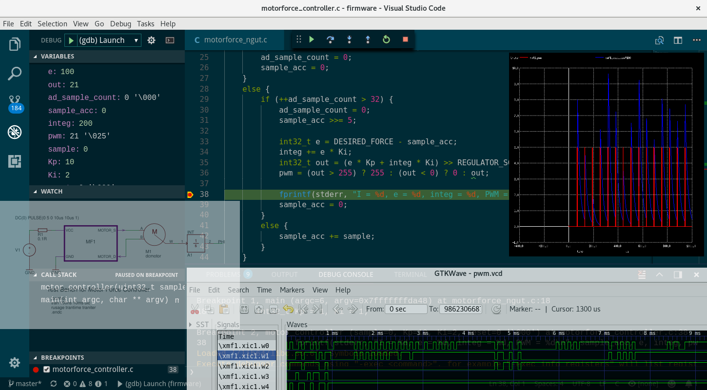
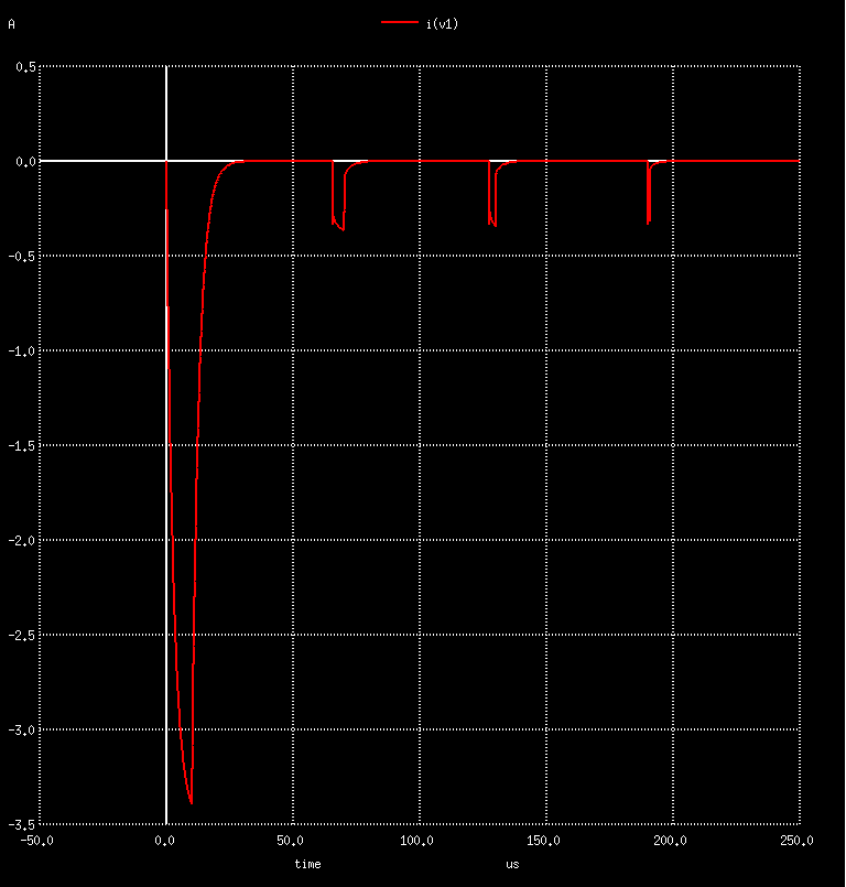
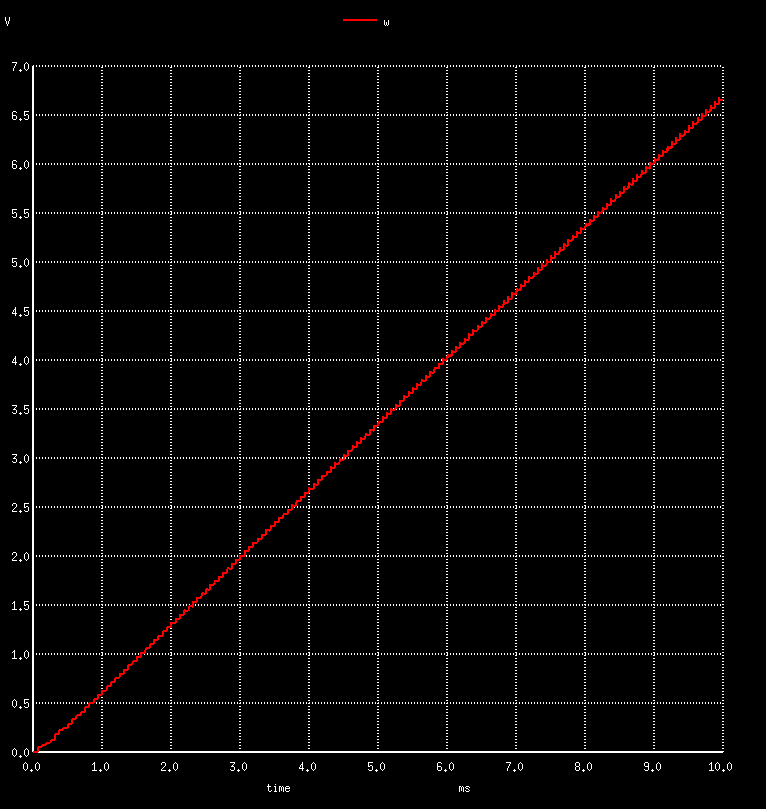
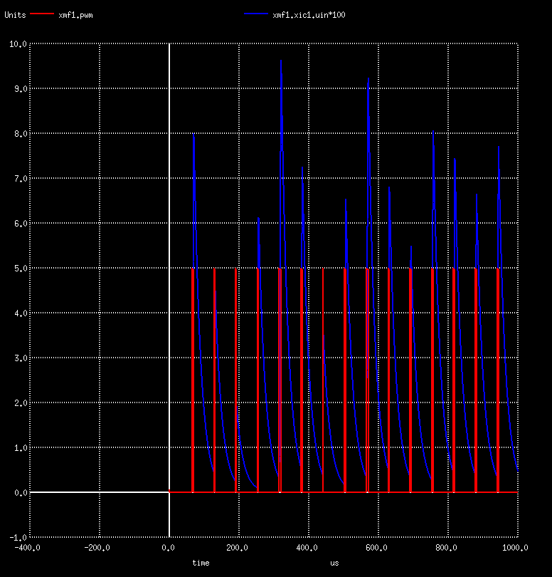
When starting a real circuit, we might first want to check the system current consumption, which may observe directly from the test bench V1: plot i(v1). Then, if the current is indeed constant, the motor acceleration should be constant as well, and the speed w must increase linearly. So, let’s plot W: plot w. Going inside the hierarchical design, we would like to see how PWM and the current sense (we magnify it by 100) are progressing: plot xmf1.pwm xmf1.xic1.uin*100. Furthermore, may directly observe, export, manipulate, and merge in-out signals from our process with ngspice signals to get the most comprehensive view on our system.
Or we may export digital signals to VCD and open it with gtkwave:
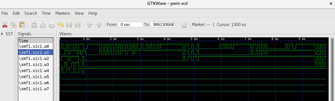
We may observe some overshooting and oscillations at the beginning, which stabilizes itself in the following cycles, with the error approaching closer to 0.
Debugging the C code
In real-time systems, it’s really hard to debug a code with conventional debuggers and stepping through it. Why? You simply cannot stop and step through the reality.
In this environment, everything is possible. Here, we are referring to a very responsive and powerful editor, the Visual Studio Code. It also knows to highlight the spice files, while its main intention is to develop, run and debug the code.
The procedure to debug the motorforce_ngut process with a debugger, like gdb, is:
use named pipes; in this way, ngspice can attach to them at any time, and we are free to start the debugger at any time.
Tell the ngspice d_process to use pipes and not to spawn a new process, by simply adding | operator at the end, so: .model firmware d_process (process_file=”firmware/motorforce_ngut|” process_params=[“Kp=10”, “Ki=2”]) An important note: in this mode, the process parameters are not passed to our process and must be entered manually when starting the debugger.
Start ngspice and the debugger; as soon as both process are started, the simulation begins.
To create named pipes on Linux:
$ mkfifo motorforce_ngut_in
$ mkfifo motorforce_ngut_out
Pass the –pipe parameter to instruct the test unit to use named pipes (fifos) instead of stdin and stdout. So like in one shell:
$ ./motorforce_ngut --pipe kp 10 ki 2
./motorforce_ngut(Kp=10, Ki=2)
Firmware Reset
I = 0, e = 100, integ = 200, PWM = 21
...
I = 99, e = 1, integ = 746, PWM = 23
I = 98, e = 2, integ = 760, PWM = 24
I = 101, e = -1, integ = 758, PWM = 23
I = 98, e = 2, integ = 762, PWM = 24
I = 101, e = -1, integ = 760, PWM = 23
I = 98, e = 2, integ = 764, PWM = 24
I = 100, e = 0, integ = 764, PWM = 23
I = 97, e = 3, integ = 770, PWM = 24
I = 100, e = 0, integ = 770, PWM = 24
I = 100, e = 0, integ = 770, PWM = 24
and in the other shell, start ngspice:
$ ngspice motor_tb.cir
....

Reference value :  9.90671e-03

No. of Data Rows : 120053
Transient analysis time = 33.353

Transient iterations = 1133372
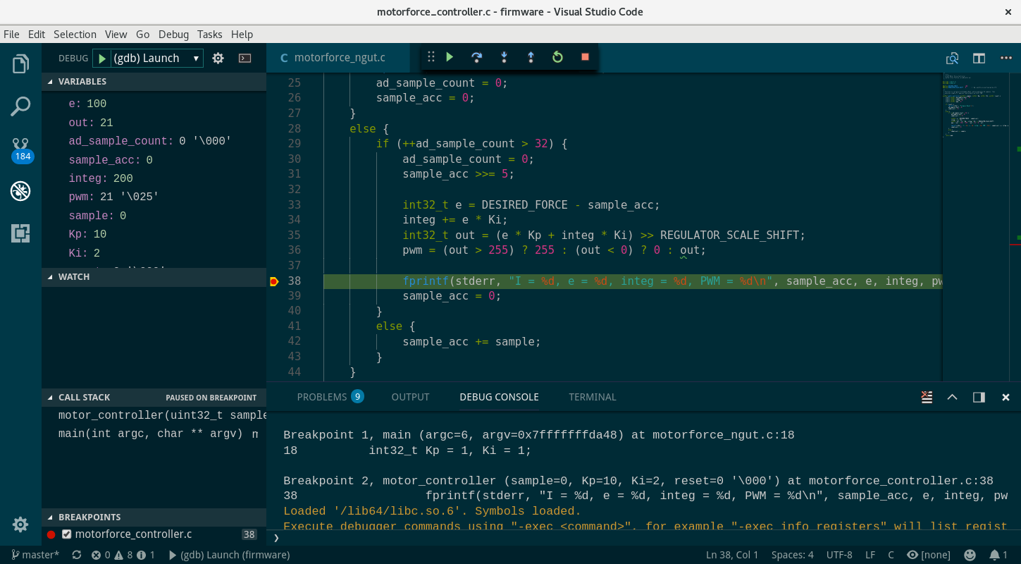
Each shell is going to report its own progress. Now, the same can be done in Visual Studio Code with the debugger. Set up the launcer.json:
 1 {
 2     "version": "0.2.0",
 3     "configurations": [
 4         {
 5             "name": "(gdb) Launch",
 6             "type": "cppdbg",
 7             "request": "launch",
 8             "program": "${workspaceFolder}/motorforce_ngut",
 9             "args": ["kp", "10", "ki", "2", "--pipe"],
10             "stopAtEntry": false,
11             "cwd": "${workspaceFolder}",
12             "environment": [],
13             "externalConsole": true,
14             "MIMode": "gdb",
15             "miDebuggerPath": "gdb",
16             "setupCommands": [
17                 {
18                     "description": "Enable pretty-printing for gdb",
19                     "text": "-enable-pretty-printing",
20                     "ignoreFailures": true
21                 }
22             ]
23         }
24     ]
25 }
Click on the debugger button on the right, start the process, set a normal or conditional break-point, and observe:
Running a Process Inside a QEMU ARM Emulator or on a Real Target
To even come closer to the actual target platform, one may use arm cross compiling tools, qemu as an arm emulator with gdb to run and/or debug the code in an actual arm environment. Here, we represent a procedure tested on Fedora (we may add another examples at your request or upon feedback), as distributions have different package names.
- On Fedora, you will need to install:
arm-linux-gnueabihf-gcc, as a cross compiling tools with gnulib support
arm-none-eabi-gdb, as arm debugger. You may search for gdb-multiarch if you do not find this one.
To start the process in a different environment, we may connect it with the ngspice on the native system with named pipes, as we have shown in the previous section. All we need to do is to recompile the above example as:
arm-linux-gnueabihf-gcc -Wall -o motorforce_ngut motorforce_ngut.c motorforce_controller.c -I../../../../include
Make sure you are using pipes in motorfw.mod, so modify the d_process line by appending | to the motorforce_ngut process_file parameter, so:
.model firmware d_process (process_file="firmware/motorforce_ngut|" process_params=["Kp=10", "Ki=2"])
And start in one terminal ngspice:
$ ngspice motor_tb.cir
....

Reference value :  9.90671e-03
And in the other process, with the path to the qemu sys-root gnulib:
$ qemu-arm-static -L /usr/arm-linux-gnueabihf/sys-root motorforce_ngut --pipe kp 10 ki 2
motorforce_ngut(Kp=10, Ki=2)
Firmware Reset
I = 0, e = 100, integ = 200, PWM = 21
I = 107, e = -7, integ = 186, PWM = 4
In order to debug inside qemu, pass the -g 6556 parameter:
$ qemu-arm-static -g 6556 -L /usr/arm-linux-gnueabihf/sys-root motorforce_ngut --pipe kp 10 ki 2
motorforce_ngut(Kp=10, Ki=2)
Firmware Reset
....
And connect to gdb remotely. Note the line target remote localhost:6556
$ arm-none-eabi-gdb motorforce_ngut
GNU gdb (GDB) 7.6.2
[cut]
warning: A handler for the OS ABI "GNU/Linux" is not built into this configuration
of GDB.  Attempting to continue with the default arm settings.

Reading symbols from /home/uros/Repos/Isotel/mixedsim.github/examples/embedded/motorforce/firmware/motorforce_ngut...done.

(gdb) target remote localhost:6556
Remote debugging using localhost:6556
warning: A handler for the OS ABI "GNU/Linux" is not built into this configuration
of GDB.  Attempting to continue with the default arm settings.

0xf67cdc00 in ?? ()
(gdb) cont
Continuing.
Cannot access memory at address 0x0
[Inferior 1 (Remote target) exited normally]
(gdb) quit
$
Extending to Real Targets
Any platform that has the ability to communicate with a host system can be integrated as a part of a ngspice simulation useful for the most demanding applications, such as the speed sensitive application where every cycle counts, safety sensitive as automotive, and aero-space and mission critical as military. The developer may therefore use their favorite target debugger, profiler, or they can even achieve an interaction with the real-world.
To integrate it as a part of simulation, write:
a simple utility that redirects stdin/stdout to your target unit,
on target side a ngspice unit test more or less of the same form as the unit test already presented above.
As the target connects to the ngspice, there are no issues with synchronization.
Conclusion
We have learned that ngspice with the Isotel d_process extension can be used as a framework for firmware development, algorithm development, unit testing in automated CI, and more. The d_process may spawn several processes, one for each firmware under testing. So when writing ngspice unit tests (ngut), keep the interface as simple as possible.
To keep the article short, we simplified it and kept away from the actually very interesting topics of motor control algorithms, signal pre-conditioning, three phase driving, sensor-less algorithms, and so on. Precision and a fast servo motor controller are seeking for wide-bandwidth and low noise current sensing controller. It is worth mentioning that we have developed an innovative current sensing theory and products the DC-CT with bandwidths over MHz and a noise level of 1 mArms in 50-100 A range.
All the project source files can be downloaded from github.
Continue to Platise Ferromagnetic (Non-Linear) Model