myLab Precision Voltmeter with Current Limited Power Supply
High accuracy, low-noise, and seamless integration with 3rd party software makes myLab
Precision Volt-meter with Power Supply an indispensable instrument in your laboratory and automated test
environments (ATE).
It is small and 10-times more cost effective than competitive instruments, suitable
for multi-channel applications.
Need a different function or a special function, then just select a another configuration.
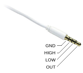
Connections
Volt-meter input is available via Sensor Jack connector via three pins, and
the 4th pin is the power supply.
- System USB Ground (GND)
- Voltage High Input Pin (High)
- Voltage Low Input (Low)
- Power Supply Output (Out) referred to Ground
Measurements are taken differentialy between the High and Low input terminals.
To the Low terminal a selectable bias voltage can be applied in the range
0..4 V to be able to measure negative voltages.
In isolated USB environment make sure that the GND terminal is connected
to your target reference in the case of differential (balanced) measurements,
or that Input.Low = Bias mode is used, to set the reference voltage potential.
- CAUTION:
- Make sure that Out is not connected to Low or High signals directly
as Power Supply voltages can go as high as 23 V, while High and Low signals
should stay within 5 V limits. If it is then pay extra attention not to
configure the supply voltage amplitude above 5 V.
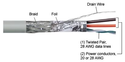
To remove noise we suggest to use a shielded cable, terminated to the GND pin at
Jack side only, and a twisted pair for High and Low signals.
An example of such cable represents a standard usb cable as shown below:
Application Programming Interface
myLab Voltmeter programming interface is inspired by a Standard Commands for
Programmable Instruments (SCPI).
Commands, states, and readings are sorted in a structure as described in the
following sub-sections.
Values represented in italic format can only be read, not settable.
Values in <…> are numerical values.
Measurements
- Measure.Voltage = <value> [V]
- Represents the latest voltage measurement.
When
Trigger.Source = Single then query this parameter to perform
a conversion.
- Measure.UTClock = <value> [ms]
- Time-stamp of the
Measurement.Voltage copied from the USB.UTClock
at the time A/D sample is available.
Power Source
- Source.Function.Shape = DC
- Currently supported output is DC only.
- Source.Function.Mode = Voltage
- Currently supported mode is Voltage source.
- Source.Voltage.Level.Immediate = <0..23> [V]
- Sets the output voltage level immediatelly.
- Source.Current.Limit.Amplitude = <0..0.5> [A]
- Current limiter.
Sense Options
- Sense.Voltage.Resolution = <20> [bits]
- Determines the resolution in bits. Future versions will allow changing
(reduction) of this parameter to gain more speed up to 10 kHz.
- Sense.Voltage.Aperture = <value> [s]
- Reflects the aperature time based on
Sense.Voltage.NPLCycles settings.
It cannot be entered.
- Sense.Voltage.NPLCycles = AC1 | NotSynced
- Determines the number of integration cycles. Currently supported is
one AC cycle or not synced to the AC line frequency
System.LFrequency.
Calculate Options
- Calculate.Average.Count = <0..255>
- Number of samples to average after A/D conversion (sensing).
- Calculate.Average.TControl = Repeat
- Clear average data and counter and restart the average process.
- Calculate.Average.Type = Scalar
- Averaging method currently supported.
Trigger Options
- Trigger.Source = Immediate | Single
- When Immediate system re-trigger immediately after conversion.
When Single a Query request to Measure.Voltage triggers next
conversion.
System Options
- System.Reset = Ok | Reset | Bootloader
- Determines the state or the last reset state.
When Ok system started successfully.
Setting to Reset will restart the system, and Bootloader option
will enter the system upgrade mode.
- System.Error = <errorCode>
- Error reporting codes.
- System.LFrequency = <50 | 60> [Hz]
- Select the line frequency in conjunction with
Sense.Voltage.NPLCycles.
- USB.UTClock = <value> [ms]
- A free running clock used to time-stamp measurements in the
Measurements.UTClock.
- myLab.VrefAccuracy = <0.10 | 0.02> %
- Displays myLab voltage reference accuracy.
Voltmeter Specifications
| Parameter |
min |
typ |
max |
Unit |
Notes |
|---|
| Voltage Measurement Range |
-0.1 |
|
Vusb-0.7 |
V |
Vusb is USB voltage (1) |
| Optional Output Reference |
0.000 |
|
4.016 |
V |
|
| Effective A/D Resolution |
|
19.5 |
|
bits |
Differential Delta-Sigma |
| Voltage Resolution |
|
11.7 |
|
uV |
One LSB |
| Measurement Accuracy |
0.02 |
0.01 |
|
% |
Adjusted |
| Long Term Stability |
|
|
|
% |
TBD |
| Input Impedance |
|
10 |
|
MOhm |
Balanced |
| Sample Rate at 16-bit |
|
|
11000 |
sps |
To be supported in FW |
| Sample Rate at 18-bit |
|
|
2400 |
sps |
To be supported in FW |
| Sample Rate (no AC rejection) |
|
22 |
178 |
sps |
178 to be supported in FW |
| Sample Rate (50 HZ rejection) |
|
|
6.25 |
sps |
|
| Sample Rate (60 HZ rejection) |
|
|
7.5 |
sps |
|
| Noise, N=1 (no averaging) |
|
17 |
|
LSB |
Peak-to-Peak |
| Noise, N=2 (averaging) |
|
14 |
|
LSB |
Peak-to-Peak |
| Noise, N=4 (averaging) |
|
7 |
|
LSB |
Peak-to-Peak |
| Noise, N=10 (averaging) |
|
5 |
|
LSB |
Peak-to-Peak |
Notes:
- Extendable to 5 V by firmware.
Power Supply Specifications
| Parameter |
min |
typ |
max |
Unit |
Notes |
|---|
| Power Supply Voltage Range |
0 |
|
23 |
V |
|
| Power Supply Current Range |
0 |
|
500 |
mA |
Total power of 2 W |
| Output Resolution |
|
20 |
|
mV |
|
| Output Accuracy |
|
50 |
|
mV |
|
Absolute Maximum Ratings
Stresses beyond these specifications may cause a harmful damage to the myLab.
| Parameter |
min |
typ |
max |
Unit |
Notes |
|---|
| Voltage Measurement Range |
-0.5 |
|
Vusb+0.5 |
V |
Vusb is USB voltage |
| Optional Output Reference |
-0.5 |
|
Vusb+0.5 |
V |
|
New Features on the way
- Power Supply Output Voltage and Current Measurements
- Voltmeter Signal Attenuation for High Voltage Measurements
- Voltmeter Programmable Input Gain Amplifier
- Synchronous Triggering (Sampling) over Multiple myLabs
- External Analog/Digital Trigger
- Voltmeter Higher Sampling Rate at Reduced Resolution
- Do you have a specific requirements?
