
Mixed Signal & Domain Simulation for Embedded Worlds
Conceptual Simulation of Digital Sine Generator from Eagle
In the Mixed Signal Introduction Article we have learnt basic principles how to combine analog and digital worlds in simulation together by using open-source tools. In this article you will learn how to use ngspice Eagle extension to do the same job but have in turn nice drawings for your documentation and presentation purposes.
Uros Platise, 6. August 2017
Hand written text files of spice circuits are in general harder to read, visualize and more erroneous. The CadSoft Eagle, recently acquired by AutoDesk, is a free to use tool for non-commercial projects, and very affordable for commercial projects. Around this cross-platform, quality software large community has been built as one can make designs from scratch to the PCB production, and can extend its functionality via User Language Programs (ULP) with ease, as an example is this ngspice ULP extension. Main idea behind ngspice extension was usability of the existing schematics by being able to annotate parts using Eagle Schematics’ attributes, from which a valid spice circuit could be generated. Conceptual designs require additional elements provided in the ngspice library, a collection of analog, digital and real-value based components originally coming from spice3f4 and xspice. In this article we focus on conceptual simulation first, so such simulation is not generated from the actual schematics. In the next article we will show how to generate spice from real schematics.
The Tools
Besides the tools mentioned under the Mixed Signal Introduction we need

AutoDesk (CadSoft) Eagle
Powerful, easy-to-use tools for every engineer includes:
Schematics Design
PCB Design
Auto-Router
User-Language Program
Various Exports and Imports for seamless integration
ngSpice Eagle Extension
Contains:
Eagle ngSpice Library
Eagle ngSpice ULP to Generate ngspice compatible circuit and sub-circuit files
Examples
ngSpice Support in the Eagle
Setting up Extension
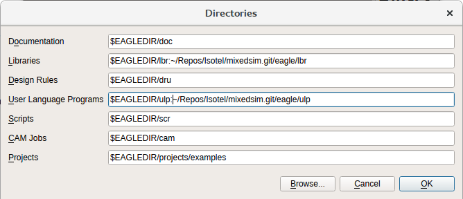
Assuming you have already installed the tools from Mixed Signal Introduction and have downloaded or cloned the mixedsim repository. Then start the eagle and add the Library and ULP directory paths under the Control->Options->Directories:
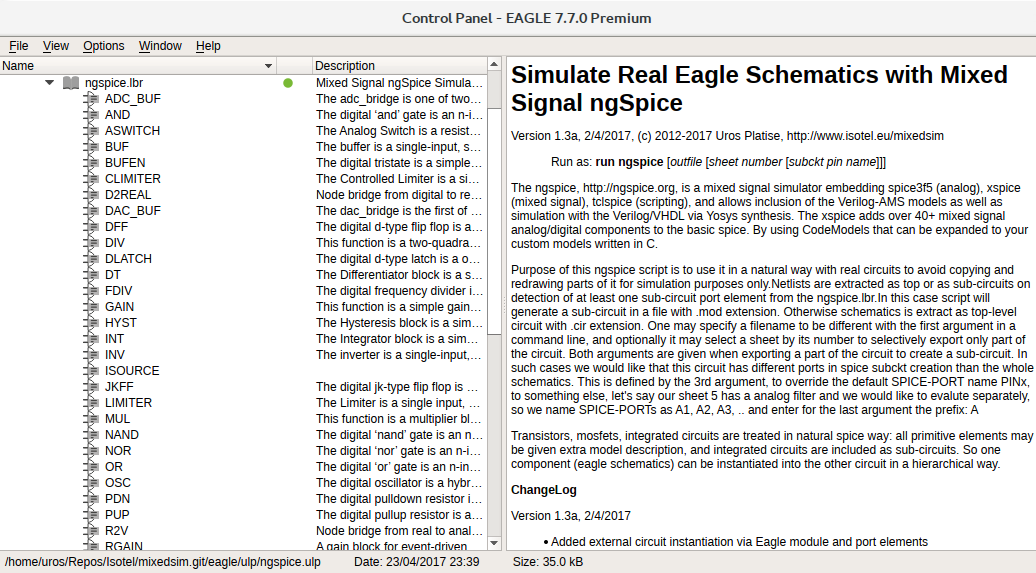
Both the ULP and the Library come with usage description. In addition each ngspice device is extensively described as per the ngspice user manual 26. It is advisable to have a copy of this user manual as Eagle ngspice library only provides description of components and not the ngspice itself.
Quick Overview
The Eagle’s ngspice support is built around the attributes. Main idea is to reuse all of the components from your existing libraries and to manually provide some of the attributes to bind them with sub-circuits or spice models to be able to simulate already made designs.
Conceptual designs may require ngspice’s specific devices which are found in the ngspice.lbr library with all of the specific attributes prepared. Shown below is the ngspice’s integrator (1/s). Attributes defaults are set to the same value as are the ngspice internal defaults.
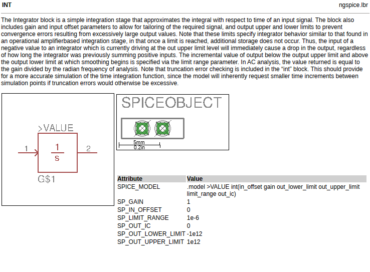
Note that the model line has a >VALUE in it to adopt the model name directly from the schematics component value. One may alter parameters of that device after placing it on the schematics by editing attributes (i.e. command: ATTR R1 to open attributes for resistor R1) and recall it at other components by specifying the same value. In this case it must add the # at the end to instructs the ULP to avoid re-creating a model line. It is of good practice to make modified attributes visible on the sheet.
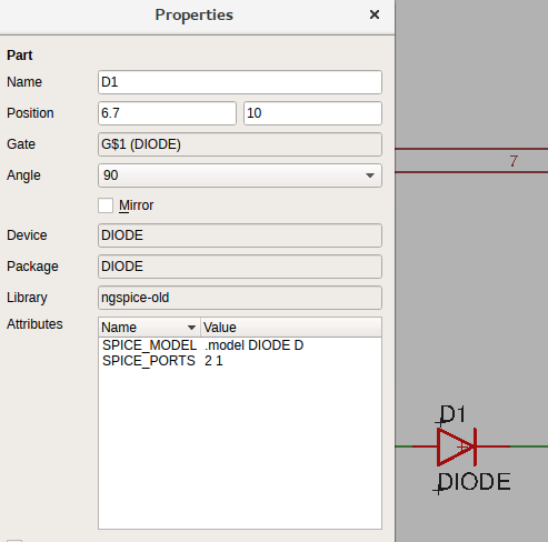
To include existing devices in the spice simulation attributes are added in the same way to define spice device, device models, amend spice value or to provide equations. Sometimes it is necessary to amend pin binding as many times the pin order of the eagle package is not the same to the spice model or sub-circuit. Or the package may even includes letters, like some of the diodes in the eagle libs have A and K, instead of numbers 1 and 2. An example of reversing pins of a diode:
Values of the L, C and R devices are parsed and converted:
if the last character is ‘R’ it is removed (as 200R -> 200)
if the last character is ‘M’ then it is changed to Meg (as 2M -> 2Meg)
a small ‘m’ is left as it is to represent mili
If value of any device equals Open then that part is ignored in the spice netlist. It may alternatively be ignored by adding it an attribute SPICE_IGNORE.
The last important thing to mention are Eagle’s component prefixes which may not necessarily represent the right meaning in the ngspice. The SPICE_DEVICE attribute may be used to set a proper ngspice prefix, and so the device model.
The ngspice.ulp is able to:
generate a top circuit, in which case the output filename has suffix .cir,
generate a sub-circuit when SPICE_PORT components are placed on the sheets, in which case the output filename has suffix .mod,
source other circuits via components by using an SPICE_INCLUDE attribute, which is automatically used for X devices, and
source other circuits via hierarchy models and the SPICE_XPORT, which allows simple inclusion of external circuits when library component is not available.
In this article we are going to use a top circuit and source a verilog module using the Eagle’s hierarchy (modules), and export the same circuitry as sub-circuit to evaluate the LPF filter performance only. Top modules in addition convert +5V, -5V, and other power nets into voltage sources to speed-up simulation process.
In the following example we will learn some more details, however for additional information click on the ngspice.ulp and ngspice.lbr files in the Eagle’s control window.
Conceptual PRS Sine Generator in ngSpice - Eagle way
Let’s repeat the design of the PRS Sine Generators as seen in the Mixed Signal Introduction Article now in the ngSpice - Eagle way.
The Analog Part with a Low Pass Filter
Use your preferred resistor, inductor and capacitor symbols, arrange them to form a LPF as shown below, and name input net as LPFIN and output net as LPFOUT:
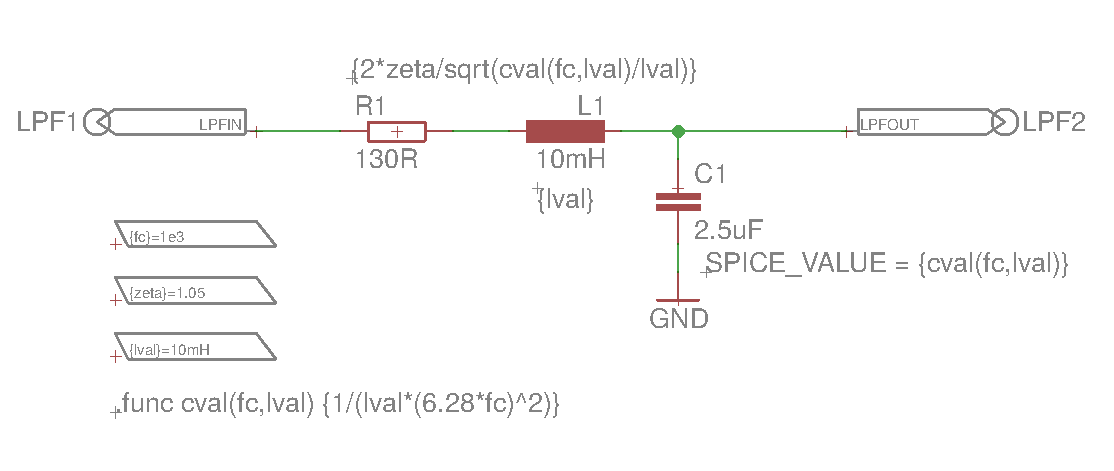
We typed in the values as found out in previous article which would be sufficient to begin with simulation. However, to make this example equal in power we have additionally added parametric equations into the SPICE_VALUE attributes which attribute overrides the part’s value, as shown for the C1, at R1 and L1 only value part of the SPICE_VALUE is shown.
To be able to make use of parametric calculation of component’s values we need to define:
SPICE-PARAM parts to provide defaults for the three parameters: fc, zeta and lval embraced in brackets, so VALUE is: {fc}=1e3 for the first and so on for the rest.
Placed definition of the function .func cval() onto the ngspice-init layer.
and to be able to selectively export this sheet of the schematics as a sub-circuit to verify it (imagine a more complex case than just a simple LPF):
SPICE-PORT part to designate in and out of the filter and we have renamed their names to LPF instead of the default PIN for sub-circuit extraction. Enter net names LPFIN and LPFOUT as VALUE of the SPICE-PORT parts to define bindings.
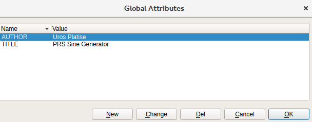
For documentation purposes we define two global attributes, go to Edit->Global Attributes and enter:
We are ready to generate as a sub-circuit spice output to verify LPF response by invoking the ngspice.ulp as:
run ngspice lpf 1 lpf
run ngspice will start the ULP if Eagle directory paths are properly set,
lpf will be the design name of the sub-circuit and output filename,
1 denotes export sheet 1 only,
the last lpf defines sub-circuit SPICE-PORT pin names, which we renamed to LPF. This allows us to individually name pins on each sheet to selectively export parts of the overall design.
The output is quite similar to what we have written manually in the previous article:
* PRS Sine Generator Sheet 1  by Uros Platise

* The prssine ngspice netlist was auto-generated on 06/08/2017 12:47
* with ngspice.ulp V1.3 for Eagle 6.5.0 - 7.7 by Uros Platise, http://www.isotel.eu/mixedsim
*
* Pin Description:
*   LPF1.        lpfin
*   LPF2.       lpfout
*
.subckt lpf lpfin lpfout lval=10mH zeta=1.05 fc=1e3

* List of Ignored and Modified Components:
*
* - C1: SPICE_VALUE = {cval(fc,lval)}
* - L1: SPICE_VALUE = {lval}
* - R1: SPICE_VALUE = {2*zeta/sqrt(cval(fc,lval)/lval)}

* Spice Initialization Directives from Sheet
.func cval(fc,lval) {1/(lval*(6.28*fc)^2)}
C1 lpfout 0 {cval(fc,lval)}
L1 1 lpfout {lval}
R1 lpfin 1 {2*zeta/sqrt(cval(fc,lval)/lval)}

* Spice Control Directives from Sheet
.ends
note the .subckt lpf … line, name equals to the design name passed as argument to the ngspice.ulp, parameters and their default values are provided from the SPICE-PARAM blocks. Clearly exposed are also the modified values from parts values as seen on a sheet, like in this example for C1, L1 and R1.
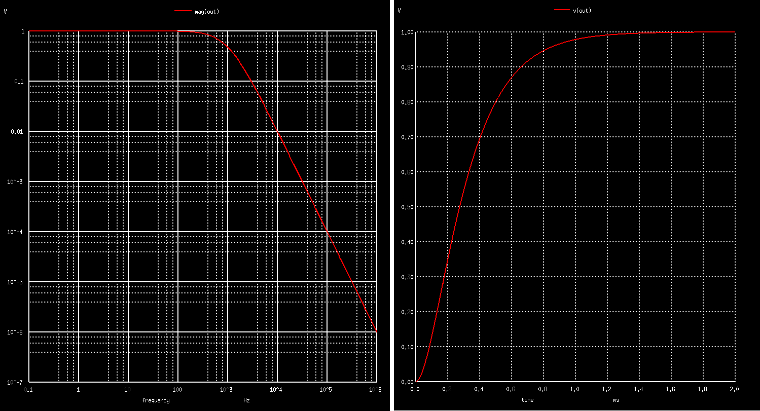
Let’s reuse the same LPF test bench and run the analysis:
* TB LPF Bode Plot

.include lpf.mod

Vac sine 0 AC 1 DC 0 PULSE(0 1 0ns, 10ns, 10ns 1s 1s)
Xlpf sine out lpf fc=1e3 zeta=1.05 lval=10mH

.control
ac dec 100 0.1 1e6
plot mag(out) loglog
plot phase(out)*180/pi xlog

tran 10ns 2ms
plot v(out)
.endc
.end
Obtained is exactly the same results as seen under Mixed Signal Introduction Article.
The Digital Part with a Verilog Module
If we want to tune or modify the LPF design afterwards and verify it as a stand-alone sub-circuit then I would recommend to leave it on its own sheet and create a new sheet to create the digital part of the design.
We begin by placing the Verilog module. It can be done in two ways, either by placing a component and bind it with an external sub-circuit or by using the Eagle hierarchical modules. We will use the 2nd method as it is faster and to avoid creating a component in a library which has no future use as a physical device.
Let’s recall the module from the previous article:
module prsgen8 (clk, rst, compare, out);
    input clk, rst;
    input [8:1] compare;
    output reg out;

    reg [8:1] sr;

    always @(posedge clk)
    begin
        if (rst) begin
            sr  <= 8'b10101010;     // initial value should be non-zero
            out <= 0;
        end
        else begin
            sr[8:2] <= sr[7:1];
            sr[1]   <= sr[4] ^ sr[5] ^ sr[6] ^ sr[8];
            out     <= (compare >= sr);
        end
    end
endmodule
which is by using the yosys synthesis translated to a sub-circuit with the following ports: clock, reset, 8-bit digital compare inputs, and single PRS digital output. Note that verilog module represents the digital nets which need bridges to the analog world.
.SUBCKT prsgen8 clk rst compare.0 compare.1 compare.2 compare.3 compare.4 compare.5 compare.6 compare.7 out
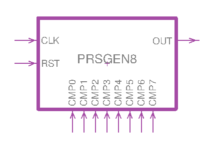
To create a module type module command and name with the same as is the Verilog module instance name, so it will be PRSGEN8. to create pins type port command. To move pins around use MOVE command and CTRL+LeftClick on port. To change its direction use INFO command and CTRL+LeftClick on port, in this way we define ins and outs. It’s for documentation purposes only.
next we bind it with the external circuitry, by editing the module accessible from the Sheet thumbnails view or use MOVE command and right click on it, you will see Edit Module below.
Place SPICE-XPORTs instances in the same order as are the pins in the spice sub-circuit and use port names, so XPIN1 corresponds to CLK, and so forth:
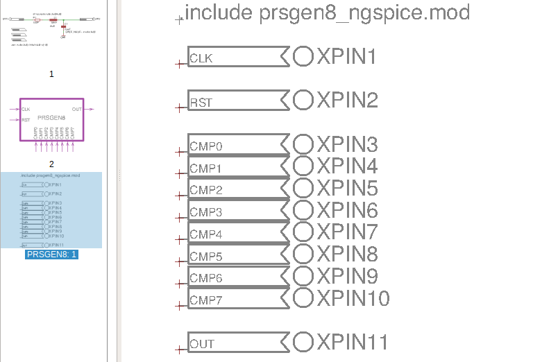
and add .include .. text block on spice layer to source external circuitry.
At any step we may check the design by generating a top-level circuit, which will include LPF and the new Verilog sub-circuit, by just running the ULP without any parameter:
run ngspice.ulp
so far the output is (having removed header, footer and comments):
.func cval(fc,lval) {1/(lval*(6.28*fc)^2)}
.param  lval =10mH
.param  zeta =1.05
.param  fc =1e3
C1 lpfout 0 {cval(fc,lval)}
L1 1 lpfout {lval}
R1 lpfin 1 {2*zeta/sqrt(cval(fc,lval)/lval)}

* Processing module PRSGEN8 from sheet 2:
.include prsgen8_ngspice.mod
Xprsgen8 null null null null null null null null null null null PRSGEN8
We may observe that LPF SPICE-PARAM values that were exported as sub-circuit parameters are now provided as default values in the circuit, and that Verilog module is ready however without any signals connected marked as null. It is a ngspice feature to describe unconnected pins.
Completing the Design
All that is left is to connect verilog instance with the output, and to provide stimulation at the input.
Keep in mind that mixed signal simulation distinguishes analog from digital nets, so bridges are necessary. In the ngspice.lbr digital signals are marked with # character, real-value signals (another variaty) with ~, and standard analog signals have no additional character inserted.
For the PRSGEN8 inputs (stimulation part) we will for a change use ngspice digital resources only, compared to the previous article in which standard analog pulsed-voltage sources are used and routed over the analog to digital bridges.
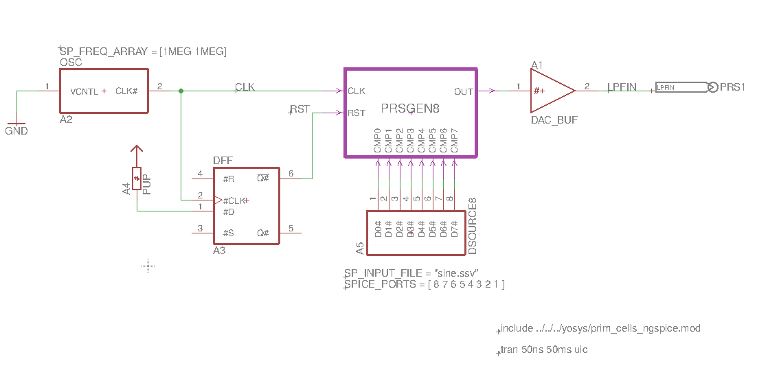
The PRSGEN8 digital output is connected to the LPF filter via the DAC_BUF component from the ngspice.lbr. The output net of the DAC_BUF has been renamed to LPFIN, to the name of the input net of the LPF input. The DAC_BUF defaults output 1 V for Logic Input High and 0 V for Logic Input Low.
Clock is generated by using the OSC device, it is a VCO which as inputs accepts analog voltage and outputs digital clock. We may tie it to ground and provide a valid clock in MHz into the SP_FREQ_ARRAY attribute as shown besides the OSC block.
Reset is generated by using a D-Flip Flop DFF with a Digital Pull-up component, also from the ngspice.lbr, to generate a short half-clock pulse sufficient for verilog module to initialize properly.
The comparator input is driven by the DSOURCE8 component which sources a stimulus vector from a file. We recall a sine wave stimulus from previous article by just specifying its input filename. In addition we had to reverse bit order. It is done by simply redefining the SPICE_PORT attribute instead of rewiring the D0-CMP7, D1-CMP6, … that would appear a bit unprofessional.
We have placed the SPICE-PORT component and named it as PRS1 to be able to export only this sheet of the schematics, just as we did for the LPF design.
We placed an .include directive to source yosys lib onto the ngspice-init layer, and transient analysis onto spice layer.
So final design is exported by running the ngspice.ulp without parameters. The generated output is found in the prssine.cir and looks like this:
PRS Sine Generator by Uros Platise

* The prssine ngspice netlist was auto-generated on 06/08/2017 15:48
* with ngspice.ulp V1.3 for Eagle 6.5.0 - 7.7 by Uros Platise, http://www.isotel.eu/mixedsim
*


* List of Ignored and Modified Components:
*
* - C1: SPICE_VALUE = {cval(fc,lval)}
* - L1: SPICE_VALUE = {lval}
* - R1: SPICE_VALUE = {2*zeta/sqrt(cval(fc,lval)/lval)}

* Spice Initialization Directives from Sheet
.func cval(fc,lval) {1/(lval*(6.28*fc)^2)}
.param  lval =10mH
.param  zeta =1.05
.param  fc =1e3
C1 lpfout 0 {cval(fc,lval)}
L1 1 lpfout {lval}
R1 lpfin 1 {2*zeta/sqrt(cval(fc,lval)/lval)}

* Auto Generated Sources

* Spice Control Directives from Sheet
* Spice Initialization Directives from Sheet
.include ../../../yosys/prim_cells_ngspice.mod

.model DAC_BUF dac_bridge(out_low=0V out_high=1V out_undef=0.5V input_load=1pF t_rise=1ns t_fall=1ns)
A1 [out][lpfin] DAC_BUF

.model OSC d_osc(cntl_array=[0 5] freq_array=[1MEG 1MEG] duty_cycle=0.5 init_phase=0 rise_delay=1ns fall_delay=1ns)
A2 0 clk OSC

.model DFF d_dff (clk_delay=1ns set_delay=1ns reset_delay=1ns data_load=1pF clk_load=1pF set_load=1pF reset_load=1pF rise_delay=1ns fall_delay=1ns ic=0)
A3 6 clk null null null rst DFF

.model PUP d_pullup( load=1pF )
A4 6 PUP

.model DSOURCE8 d_source(input_file="sine.ssv" input_load=1e-12)
A5 [13 12 11 10 9 8 7 5] DSOURCE8

* Processing module PRSGEN8 from sheet 2:
.include prsgen8_ngspice.mod
Xprsgen8 clk rst 5 7 8 9 10 11 12 13 out PRSGEN8

* Auto Generated Sources

* Spice Control Directives from Sheet
.end
Running it we may see the result as already seen in the previous article:
$ ngspice prssine.cir
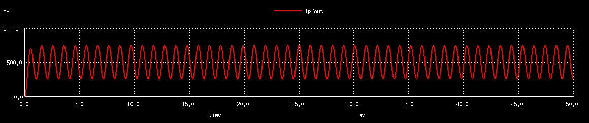
ngspice -> run
ngspice -> plot lpfout
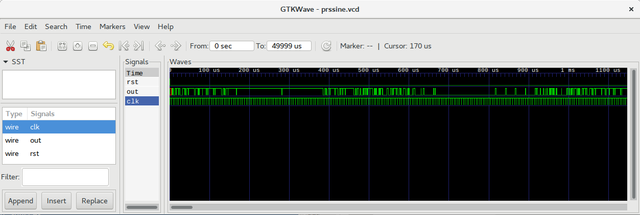
The same instruction plot is used to plot digital signals i.e. type: plot clk rst or alternatively export signals with an undocumented command to a vcd formatted file by:
ngspice -> eprvcd clk rst out > prssine.vcd
Conclusion
We have learnt how to do mixed signal simulation that includes, analog, digital and external verilog module. In the next article we will learn how to apply the same principles to a real PCB design using a micro-controller.
The whole project source files can be downloaded from github.