
Mixed Signal & Domain Simulation for Embedded Worlds
Demo Project - Digital Sine Generator with PRS and Low-Pass Filter
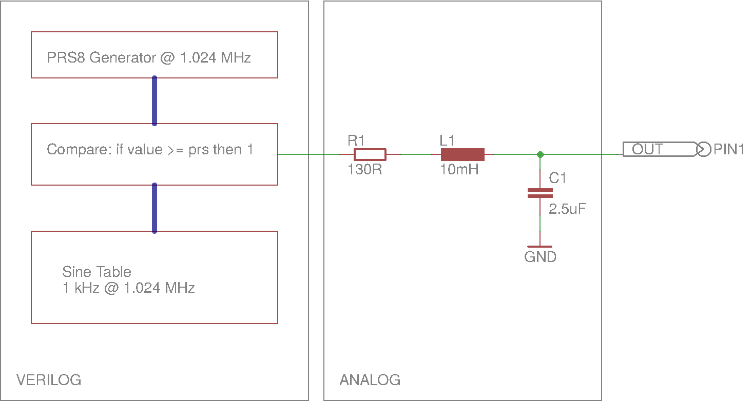
To demonstrate a mixed signal simulation with the Verilog let’s make a 1 kHz sine generator by using a 8-bit pseudo-random-sequence (PRS) generator running at 1 MHz. The digital output of the PRS generator is then driving a 2nd order low-pass filter described with spice standard analog components.
PRS8 Generator in Verilog
Let’s first develop a verilog module for an 8-bit PRS generator which is composed of a shift register (sr) with linear feedbacks composed of simple xor functions, as shown in the following figure:
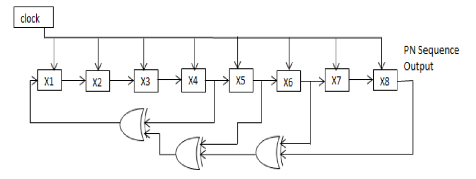
As PRS generates a finite stream of numbers in range 1..255 equally distributed. In addition we add a compare function, which turns one digital output pin high whenever a value in the shift register (sr) is less the value of the compare input. This will create a stream of high pulses proportional to the compare value.
Code looks like this:
module prsgen8 (clk, rst, compare, out);
    input clk, rst;
    input [8:1] compare;
    output reg out;

    reg [8:1] sr;

    always @(posedge clk)
    begin
        if (rst) begin
            sr  <= 8'b10101010;     // initial value should be non-zero
            out <= 0;
        end
        else begin
            sr[8:2] <= sr[7:1];
            sr[1]   <= sr[4] ^ sr[5] ^ sr[6] ^ sr[8];
            out     <= (compare >= sr);
        end
    end
endmodule
We could directly instantiate a verilog module into the ngspice, however let’s make sure the module is performing correctly, by verifying it using the iverilog first. To do so, we need to write a test bench, to provide clock, reset, and compare value, to be able to observe the prs output.
module prsgen8_tb;
    reg reset = 0;
    reg clk = 0;
    wire out;

    /* Make a reset pulse and specify dump file */
    initial begin
        $dumpfile("prsgen8_tb.vcd");
        $dumpvars(0, prsgen8_tb);

        # 0 reset = 1;
        # 2 reset = 0;
        # 1024 $finish;
    end

    /* Make a regular pulsing clock. */
    always #1 clk = !clk;

    prsgen8 prs(clk, reset, 8'hfe, out);
endmodule
As shift register value range is between 1..255 means if:
compare value is 255 the output will be always 1
compare value is 0 the output will be always 0
Let’s observe the output for 254, which should show one low pulse in a periodic stream with distance of 255 clocks, the 8-bit PRS period. Compile and run the code:
iverilog -o prsgen8_tb prsgen8_tb.v prsgen8.v
./prsgen8_tb
And review results using the gtkwave:
gtkwave prsgen8_tb.vcd
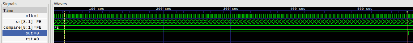
We may observe first low pulse at 53 and second low pulse at 563. As clock is low for one step and high for another step means that 563-53 equals 510 steps, or 255 cycles. This proves the implementation of the PRS8.
Now let’s change compare value to the middle by modifying the line in the test bench:
prsgen8 prs(clk, reset, 8'h80, out);
Compile and run the code:
iverilog -o prsgen8_tb prsgen8_tb.v prsgen8.v
./prsgen8_tb
and in the gtkwave press CTRL+SHIFT+R to reload the waveform.
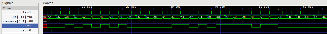
We may observe:
undefined states at the beginning of the simulation,
on clock rising edge and reset being high, register preset, shift register with some non-zero value and output is cleared.
follows a non-monotonic counting in a PRS8 way,
and compare output is high when compare value is above or equal the value in the shift register.
It’s time to design a filter with analog parts.
Analog Low-Pass Filter
We begin with the design of a 2nd order RLC filter by setting the cut-off frequency at the desired 1 kHz sine output. Instead of manually calculating R,L,C values of the filter we will enter the equations into the ngspice low-pass filter sub-circuit. Filter design parameters are cut-off frequency fc, zeta and desired inductor value. Sub-circuit code in ngspice looks like this:
.func cval(fc,lval) {1/(lval*(6.28*fc)^2)}

.subckt lpf in out fc=10e3 zeta=1 lval=100uH

R in lin  {2*zeta/sqrt(cval(fc,lval)/lval)}
L lin out {lval}
C out 0   {cval(fc,lval)}

.ends
We set zeta to ~1 critically damped, cut-off frequency of 1 kHz and inductor of 10 mH. Putting it all together in a ngspice test bench to obtain bode and pulse response:
* TB LPF Bode Plot

.include lpf.mod

Vac sine 0 AC 1 DC 0 PULSE(0 1 0ns, 10ns, 10ns 1s 1s)
Xlpf sine out lpf fc=1e3 zeta=1.05 lval=10mH

.control
ac dec 100 0.1 1e6
plot mag(out) loglog
plot phase(out)*180/pi xlog

tran 10ns 1ms
plot v(out)
.endc
.end
Let’s run above code:
ngspice lpf_tb.cir
and bode and transient response plots appear on the screen:
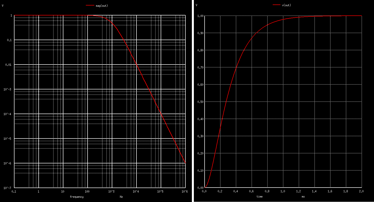
Instead of reading values from the plots ngspice offers another powerful measure command to read out values at desired points, i.e. to find out attenuation at 1 kHz type:
ngspice -> setplot ac1
ngspice -> meas ac fs_dB find vdb(out) at=1e3
fs_dB               =  -6.448791e+00
In this design we are ok if the output signal a bit attenuated. Next we would like to know what are the actual values of the RLC filter, calculated via RLC equations. We may find them by typing:
ngspice -> listing expand
...
11 : r.xlpf.r sine xlpf.lin   1.31879999999999967e+02
12 : l.xlpf.l xlpf.lin out    1.00000000000000002e-02
13 : c.xlpf.c out 0           2.53559982149377236e-06
so C=~2.5 uF, and R=~130 Ohm and inductance was given as input parameter L=10mH. So we’re ready for the next step, to instantiate verilog code into the ngspice simulator.
1 kHz Sine Generation with Verilog & ngSpice Mixed Signal Simulation
Let’s convert the verilog code into the ngspice by doing the synthesis of the prsgen8 verilog module by using the yosys set of tools:
read_verilog prsgen8.v
read_verilog -lib ../../yosys/prim_cells.v

proc;; memory;; techmap;;

dfflibmap -liberty ../../yosys/prim_cells.lib
abc -liberty ../../yosys/prim_cells.lib;;

write_verilog prsgen8_syn.v
write_spice -neg d_low -pos d_high prsgen8_ngspice.mod

show
The first part is about elaborating the verilog code, then processing, optimizing, fitting to the technology cells and finally there is an output in the spice netlist format. We add the suffix _ngspice since code is adapted to work with ngspice.
All above commands are stored in a single file called prsgen8_ngspice.ys to be able to execute synthesis with a simple call:
yosys prsgen8_ngspice.ys
The synthesis output can be nicely reviewed with the graphviz (note the show command above):

The synthesized code contains primitives, logic gates and basic flip-flops, as seen in the generated module output. Note the first line which defines the order of arguments of the generated verilog component:
.SUBCKT prsgen8 clk rst compare.0 compare.1 compare.2 compare.3 compare.4 compare.5 compare.6 compare.7 out
X0 sr.0 1 NOT
X1 sr.1 2 NOT
X2 sr.2 3 NOT
X3 sr.3 4 NOT
X4 sr.5 5 NOT
X5 sr.6 6 NOT
X6 compare.1 7 NOT
X7 compare.2 8 NOT
X8 compare.3 9 NOT
X9 compare.4 10 NOT
X10 compare.5 11 NOT
X11 compare.6 12 NOT
X12 compare.7 13 NOT
X13 sr.0 rst 14 NOR
X14 14 15.1 NOT
X15 2 rst 15.2 NOR
X16 sr.2 rst 16 NOR
X17 16 15.3 NOT
X18 4 rst 15.4 NOR
X19 sr.4 rst 17 NOR
X20 17 15.5 NOT
X21 5 rst 15.6 NOR
X22 sr.6 rst 18 NOR
X23 18 15.7 NOT
X24 sr.3 sr.4 19 NAND
X25 19 20 NOT
X26 sr.3 sr.4 21 NOR
X27 21 22 NOT
X28 19 22 23 NAND
X29 20 21 24 NOR
X30 sr.5 sr.7 25 NAND
X31 25 26 NOT
X32 sr.5 sr.7 27 NOR
X33 27 28 NOT
X34 25 28 29 NAND
X35 26 27 30 NOR
X36 23 30 31 NOR
X37 24 29 32 NOR
X38 31 32 33 NOR
X39 rst 33 15.0 NOR
X40 sr.7 13 34 NOR
X41 2 compare.1 35 NAND
X42 1 compare.0 36 NOR
X43 35 36 37 NAND
X44 sr.3 9 38 NAND
X45 sr.2 8 39 NOR
X46 sr.1 7 40 NAND
X47 3 compare.2 41 NOR
X48 37 40 42 NAND
X49 39 41 43 NOR
X50 38 43 44 NAND
X51 42 44 45 NOR
X52 38 39 46 NAND
X53 sr.3 9 47 NOR
X54 sr.4 10 48 NOR
X55 47 48 49 NOR
X56 46 49 50 NAND
X57 45 50 51 NOR
X58 sr.5 11 52 NAND
X59 sr.4 10 53 NAND
X60 52 53 54 NAND
X61 51 54 55 NOR
X62 6 compare.6 56 NAND
X63 5 compare.5 57 NAND
X64 56 57 58 NAND
X65 55 58 59 NOR
X66 sr.7 13 60 NAND
X67 sr.6 12 61 NAND
X68 60 61 62 NAND
X69 59 62 63 NOR
X70 34 63 64 NOR
X71 rst 64 65 NOR
X72 clk 65 out DFF
X73 clk 15.0 sr.0 DFF
X74 clk 15.1 sr.1 DFF
X75 clk 15.2 sr.2 DFF
X76 clk 15.3 sr.3 DFF
X77 clk 15.4 sr.4 DFF
X78 clk 15.5 sr.5 DFF
X79 clk 15.6 sr.6 DFF
X80 clk 15.7 sr.7 DFF
.ENDS prsgen8
Next is to write a top ngspice circuit which includes:
verilog prs8 generator and the technology primitive cells,
low pass filter,
analog to digital and digital to analog bridge to connect the two worlds,
to provide 1.024 MHz clock and reset pulse at the beginning,
and to provide sine stimulus as 8-bit table in time.
Here is the code:
.include ../../yosys/prim_cells_ngspice.mod
.include prsgen8_ngspice.mod
.include lpf.mod

* A/D and D/A Bridge Models
.model adc_buff adc_bridge(in_low = 0.8 in_high=2)
.model dac_buff dac_bridge(out_high = 5)

* Analog Stimulus 1 MHz clock with one cycle reset pulse
Vclk clk 0 PULSE(0 4.9 500ns 50ns 50ns 438.28ns 976.56ns)
Vrst rst 0 PULSE(0 4.9 0 50ns 50ns 2us)

* Digital Stimulus with 8-bit Sine Input
.model sine_stimulus d_source(input_file = "sine.ssv")
Asine [s7 s6 s5 s4 s3 s2 s1 s0] sine_stimulus

* PRS Generator with LPF and D/A Bridge
Xprs dclk drst s0 s1 s2 s3 s4 s5 s6 s7 dprsout prsgen8
Aad [clk rst] [dclk drst] adc_buff
Ada [dprsout] [prsout] dac_buff

Xlpf1 prsout out lpf fc=1e3 zeta=1.05 lval=10mH

.control
tran 10ns 50ms uic
plot v(clk)+10 v(rst)+15 v(prsout)+5 v(out)

linearize v(out)
fft v(out)
plot mag(out) ylog
.endc
.end
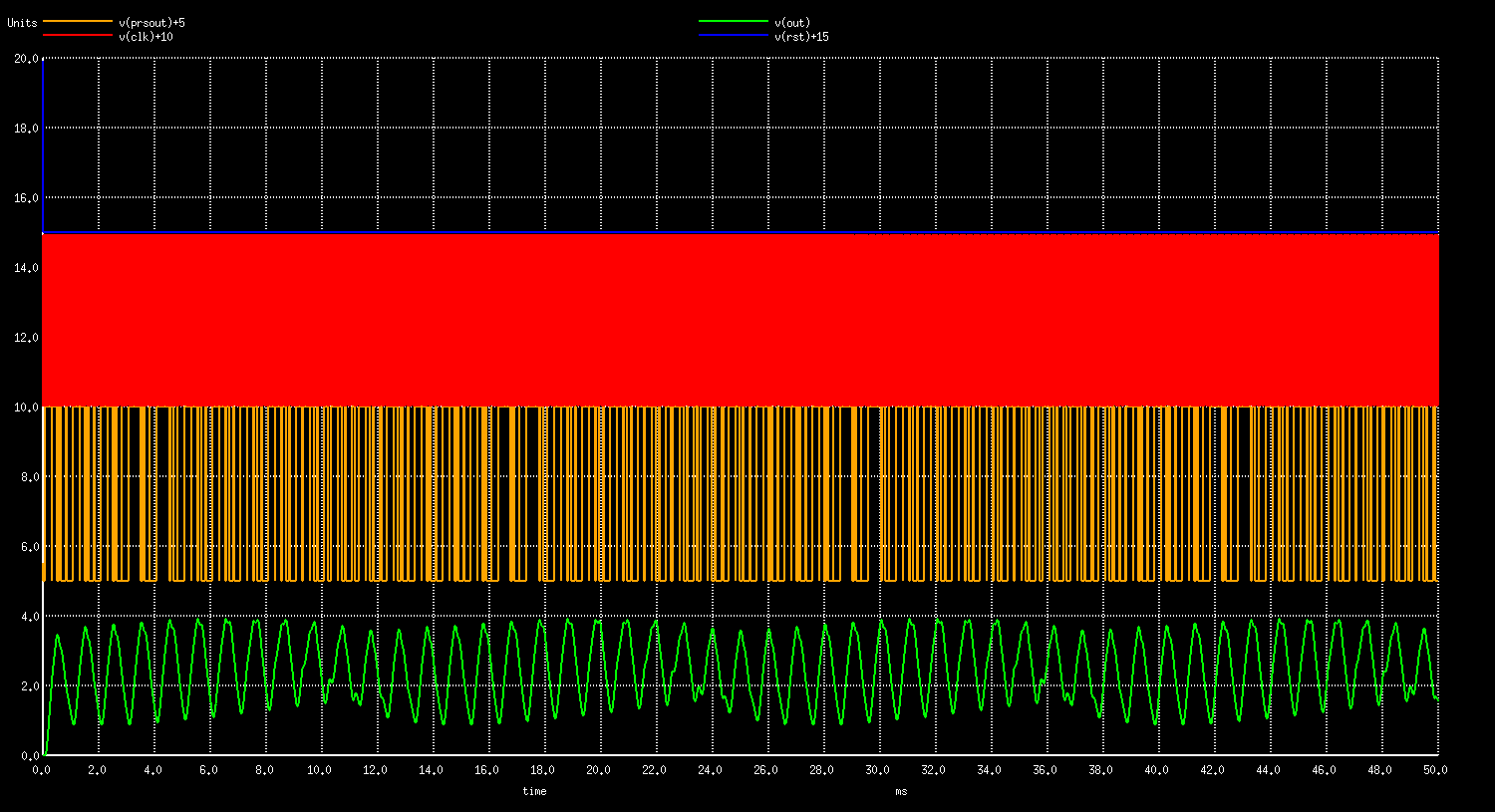
Let’s run it and plot will appear on the screen:
ngspice prssine.cir
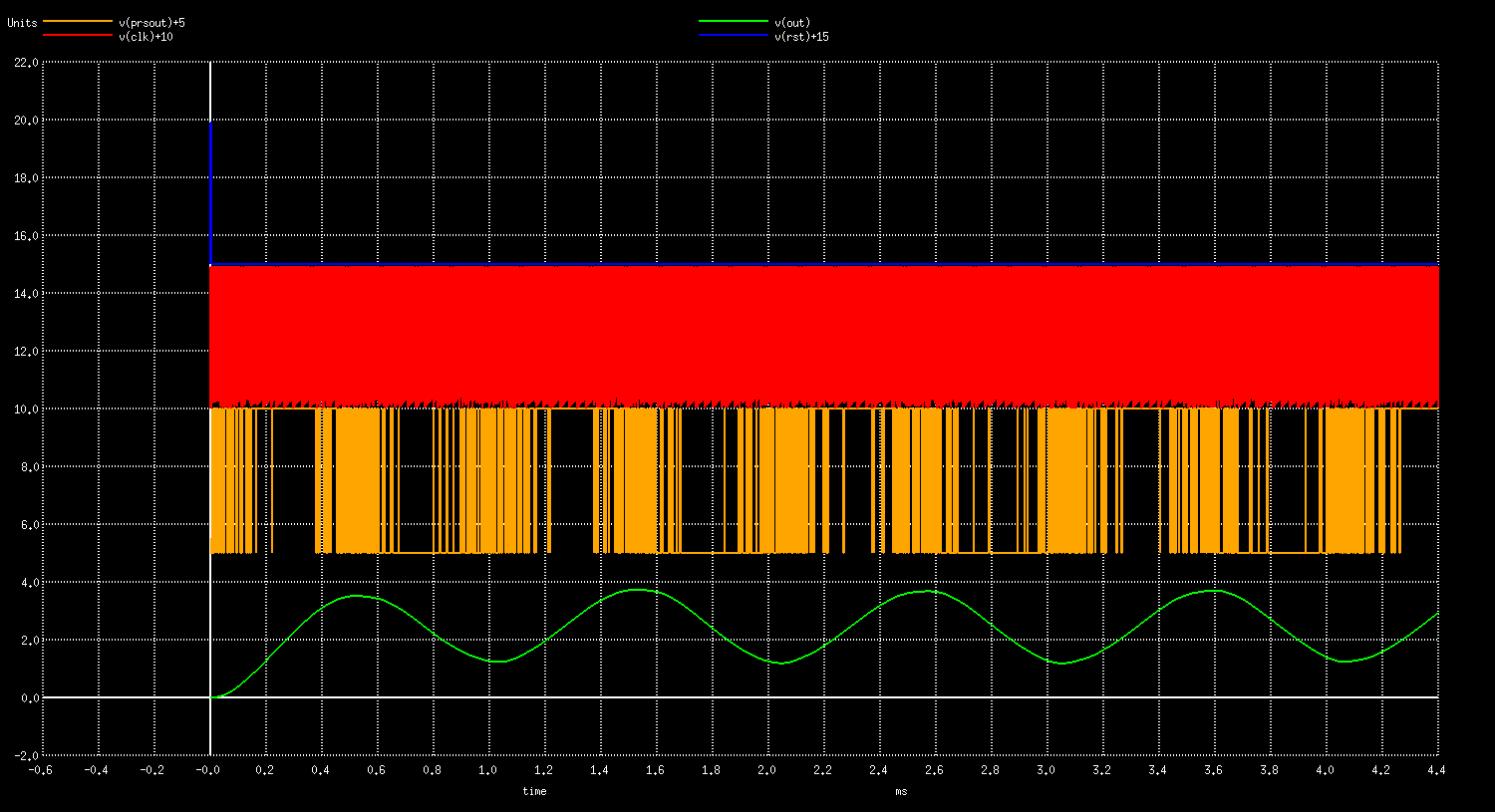
From the top there is a reset pulse in blue, red is the clock, orange is the PRS8 output just before the filter and green is the filtered sine wave.
Let’s zoom it out to see how it appears on larger scale with the frequency spectrum:
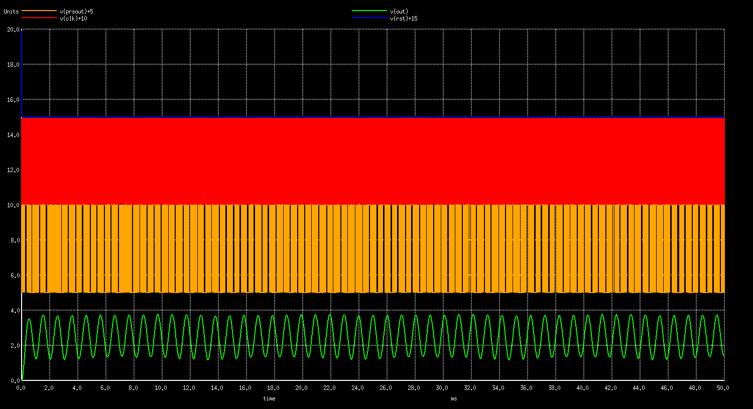
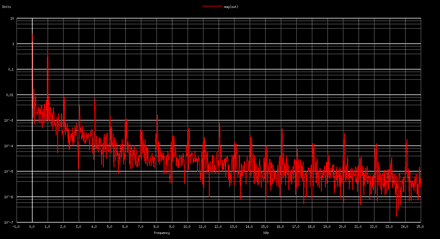
The ratio between the PRS8 clock of 1.024 MHz and the output sine of 1.000 kHz is relatively low of only 1024 digital 1,0 pulses per entire sine wave period. To obtain better results increase this ratio, or add additional filtering at the output. We should also mention the importance of voltage stability of a digital output pin with overall impact on gain stability and accuracy.
However let’s compare performance with the traditional PWM found in every MCU’s. To do so, modify the following lines in the prsgen verilog file, synthesize the ngspice module and run the ngspice again.
else begin
    sr <= sr + 1;
    //sr[8:2] <= sr[7:1];
    //sr[1]   <= sr[4] ^ sr[5] ^ sr[6] ^ sr[8];
    out     <= (compare >= sr);
end
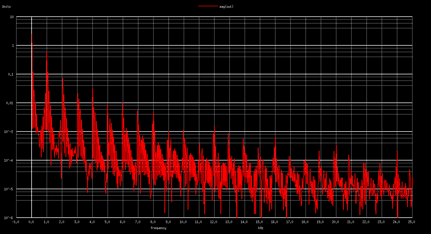
Harmonics Comparison:
Frequency [kHz] |
PRS8 [dB] |
PWM8 [dB] |
|---|---|---|
1 |
-4.4 |
-4.8 |
2 |
-42 |
-23 |
3 |
-49 |
-33 |
4 |
-43 |
-30 |
5 |
-57 |
-41 |
We may quickly notice that the PWM is performing much worse at the same clock frequency as the PRS8 for about 16 dB at each harmonic. In addition the PWM implementation requires more hardware resources than the PRS generator.
Synthesis comparison of digital resource utilization:
Resource |
PRS8 |
PWM8 |
|---|---|---|
NAND cells |
21 |
29 |
NOR cells |
30 |
30 |
NOT cells |
21 |
21 |
internal signals |
68 |
124 |
input signals |
17 |
17 |
output signals |
9 |
9 |
In a very similar way delta-sigma modulation transforms a n-bit input to m-bit output and is nowadays the most popular way of signal acquisition and generation also in audio/sound areas offering greatest THD and SNR ratios.
It’s true that most of the MCUs come with the PWM timer blocks only, however it is worth mentioning Cypress PSoC families featuring PRS blocks from 8 to 32-bit and internal configurable analog blocks that may directly implement above case, and provide analog signal at the output.
Conclusion
With this demo we concluded the introduction to the mixed signal simulations with verilog, and an interesting example of using PRS generators in analog signal generation.
Tools used in this project are all open-source based on free to-use license. Synthesis and simulation tools can run in batch mode, giving opportunities for background simulation in a complex simulation systems running on numerous server units.
The whole project source files can be downloaded from github.